


SCR.POWER.REGULATOR
|
SCR.POWER.REGULATOR ●Product Features
● With a variety of control input signal selection (4~20mA/0~20mA/0- 5V/0~10V/1~5V /2~10V) switchable choose
● With internal power output manual adjustment and external output power manual adjustment + automatic adjustment
● Has a fuse open Indicator/load short open indicator (optional) / SCR overheating(85℃) indicators and abnormal alarm contact
● With load output power 0~100% shows the percentage of
● With load buffer heating time adjustment (1~25 sec)
● Have instant when you start the power resulting in instantaneous overcurrent protection circuit (SCR fuse is not burned)
● SCR overtemperature or FUSE fuse immediately stop output,when troubleshooting pending restoration,then buffered output
● Built FAST fuse、protection SCR no damage (fuses and easy disassembly)
● Ultra-high efficiency heat sinks,thermal type fast、good heat dissipation
● Power frequency self-detection,50~60 Hz can be used,without any selection or switch
● Main power adopt a single standard design 200V~480V within the scope of the use of either
● Control signal terminal block、european mining detachable terminal block,replacementcontrol loop can avoid re-wiring |
||||||||||||||||
 |
● Product Specifications Applied voltage: Three-phase voltage AC200V~480V 10% 50/60Hz(R.S.T)
Auxiliary current: AC220V 10% 50/60Hz (PC Board AC1/AC2)
Input signal: 4~20mA,0~10V signal etc
Use of the environment: Temperature-10~55 humidity90% RH the following
Compressive strength: AC2000V/1 minute (between supply-side fins)
Insulation resistance: 20mMn the above/500V (between supply-side fins) |
|||||||||||||||
|
█ Control methods and applicable load
Phase Control:Continuity intersection control,output stability,ammeter does not shake,but every Zhouban Bo will produce harmonics |
||||||||||||||||
|
█ Wiring and Planning Considerations |
||||||||||||||||
 |
 |
|||||||||||||||
|
NFB→ Turn off the power in the repair and maintenance avoid personal contact
|
||||||||||||||||
|
● Standard main loop planning: Main Power→No fuse switch→Electromagnetic |
||||||||||||||||
| SCR.POWER.REGULATOR | |||||||||||||||||||||||||||||||
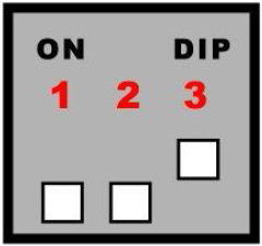
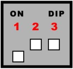
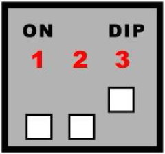
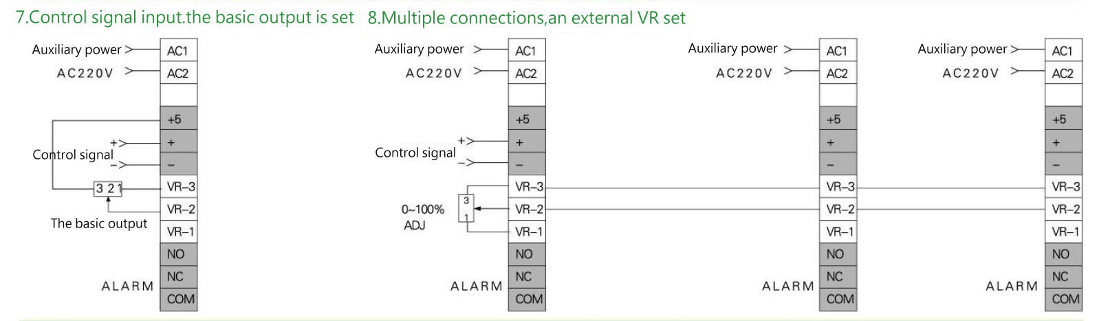
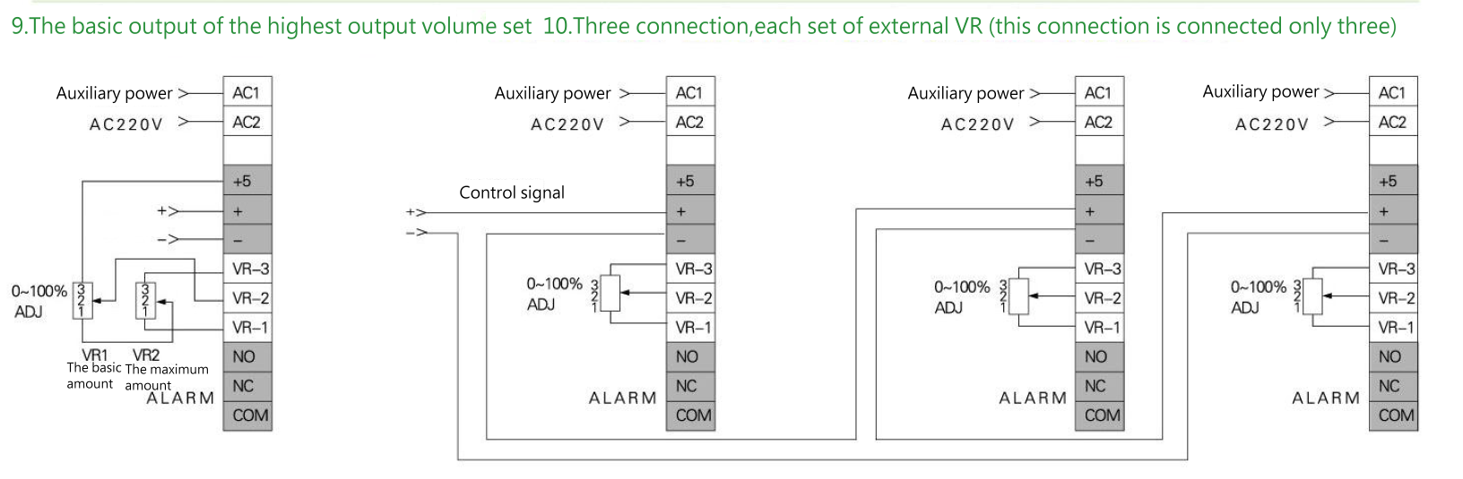
| █ Select the input signal | |||||||||||||||||||||||||||||||
| Input Signal 4~20mA、 0~20mA、Manually VR adjust manual (1-ON/2-OFF) |
Input Signal1~5v、 DC、0~5v DC (1-ON/2-OFF) |
Input Signal 2~10v、DC、0~10v DC (1-OFF/2-ON) |
Abnormal automati cally boot(3-ON) |
||||||||||||||||||||||||||||
 |
 |
 |
 |
||||||||||||||||||||||||||||
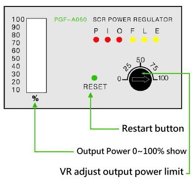
| █ Adjustment function Display and troubleshooting | |||||||||||||||||||||||||||||||
| ① VR1 BIAS: Reference output voltage adjustment(counterclockwise to adjust the control signal the smaller input to outpu) ② VR2 MAX: The maximum output voltage adjustment (adjustment range 0~100% counterclockwise adjustment Reduce the amount of full output do not zerootherwise there will be no output) ③ VR3 SFS: Buffer rise time adjustment (adjustment 0~25 seconds clockwise to adjust the buffer between the increase) ④ VR4 R phase: R phase adjustment ⑤ VR5 T phase: T phase adjustment |
|||||||||||||||||||||||||||||||
 |
 |
||||||||||||||||||||||||||||||
|
█ VR-100%: Output Power 0~100% If █ RESET: Return built (restart) █ %:Output Power 0~100% display lights |
|||||||||||||||||||||||||||||||
|
|||||||||||||||||||||||||||||||
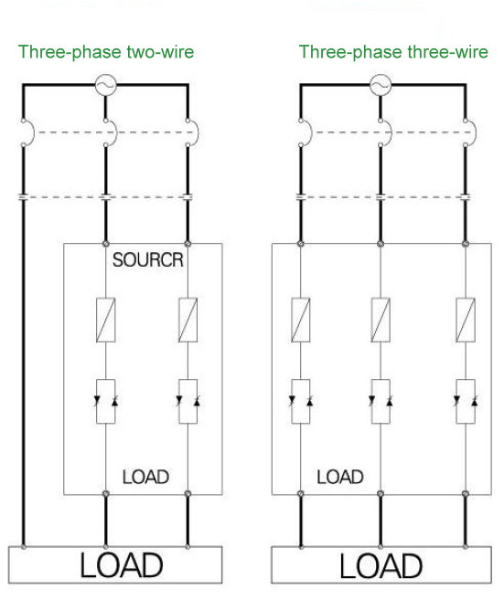
| █ Three-phase three-wire phase、three-phase two-wire zero wiring example | ||||||||||||||||||||||||||||||||||||||||||||
| The main loop road map | ||||||||||||||||||||||||||||||||||||||||||||
 |
||||||||||||||||||||||||||||||||||||||||||||
 |
||||||||||||||||||||||||||||||||||||||||||||
 |
||||||||||||||||||||||||||||||||||||||||||||
 |
||||||||||||||||||||||||||||||||||||||||||||
|
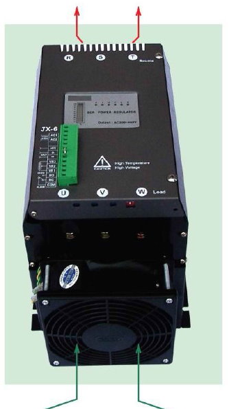
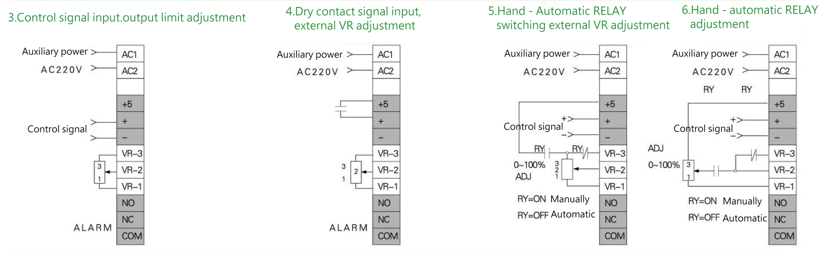
█ Terminal Board Description
|
||||||||||||||||||||||||||||||||||||||||||||
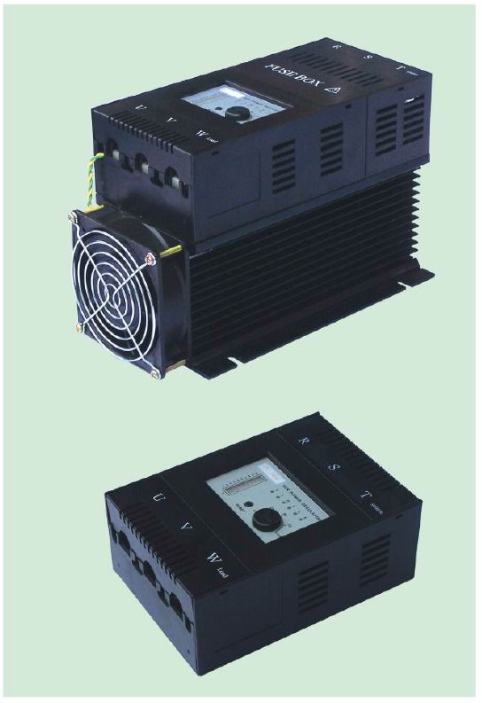
| █ Appearance Description | ||||||||||||||||||||||||||||||||||||||||||||
 |
||||||||||||||||||||||||||||||||||||||||||||
 |
||||||||||||||||||||||||||||||||||||||||||||
| █ Dimensions | ||||||||||||||||||||||||||||||||||||||||||||
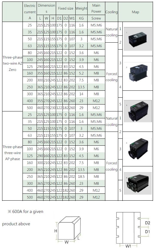 |
||||||||||||||||||||||||||||||||||||||||||||